Toys4Therapy
Documentation
Week 12
Week 13
Week 11
Introduction
Documentation
Trail of Evidence
Recess
Week 14
Trail of Evidence
Documentation
Week 15
Trail of Evidence
Documentation
Week 16
Trail of Evidence
Documentation
Week 17
Documentation
Trail of Evidence
Week 18
Trail of Evidence
Documentation
Week 19
Trail of Evidence
Documentation
Week 20
Trail of Evidence
Documentation
After the main board was programmed with a basic version of the final program the final assembly began. All Led boards were connected to Power, ground, LED data and a row and column wire for the switches.
Originally we intended the led boards to be mounted with screws, but because some of acrylic studs were misaligned we opted to glue them using hotglue.
Programming the main board
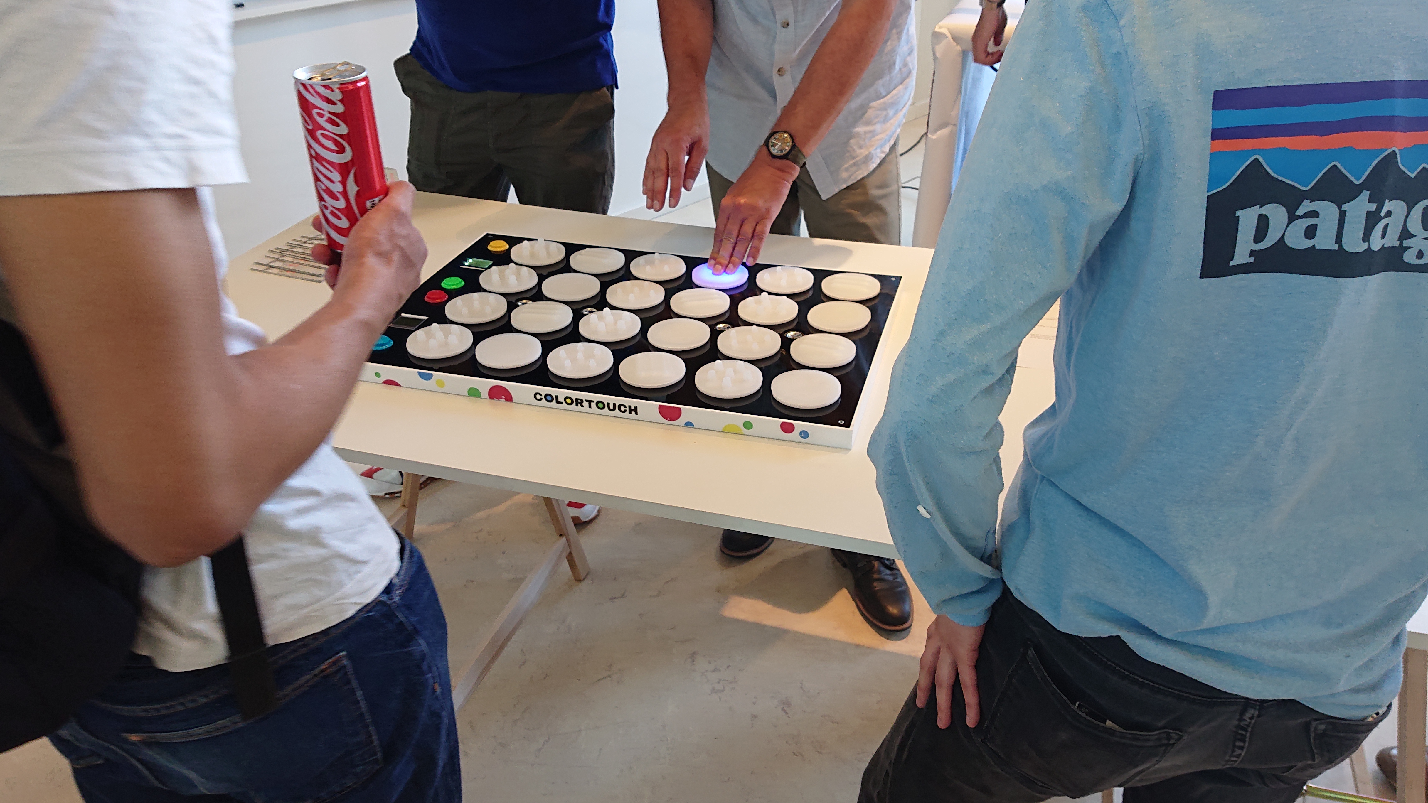
The final product
The final working project was displayed on the makerslab expo. It was received positively although people did remark on the potential to further optimize the software. We saw people having fun while playing with the project, which was verification for us that we did well.
Attaching the string of circuit boards to the bottom with a glue gun
Testing if the components would fit
On the circuit boards RGB leds, a button and wires had to be soldered
Working at Wouter's school
Printing with UV printer on a transparante vinyl sticker
Design for the side
Mainboard is working!
Trail of Evidence
Finishing touch
In order to really finish the product, we made a design for the side of the product. We bought a sheet of vinyl sticker at "Vlieger Papier". The design was printed with the UV printer on the sheet of vinyl sticker. This was then cut out and glued to the side. The design could also be printed directly on the side, only in our case everything was already glued together with acetone. Something we can take into account for the future.
The code consists mostly of original code but some existing projects were incorporated.
The code that runs on the ATTiny 861A is a slightly modified version of the code written by Elm-Chan.
Since his code already has everything you could ask for, and has parts of it written in the very efficient AVR assembly language.
His project can be found here: http://elm-chan.org/works/sd20p/report.html
The displays are controlled by the PCD8544 library written by Sylvain Bissonette. The library was originally intended for ATMega microcontrollers so it was modified to work with the hardware SPI and GPIO's of the XMega.
The main code was written while being severely short on time. Normally you would spend time to make a program more structured, dynamic and elegant.
The led control functions were implemented using bit banging. Normally you would write such a function in assembly language because assembly always executes one command per clock cycle and thus allows you to calculate exactly when to modify the pin outputs. Because there was little time I wrote my functions in C and used an oscilloscope to get the timing right.
The buttons make use of a row and column topology. In practice this means that one row is pulled high at a time. Subsequently all the column inputs are scanned, if one of the inputs registers a high signal, we know that button is pushed. This process is repeated until all the rows are processed.
At the moment the game element is hardcoded. The green button is pushed to start a new game. The display indicated which hands should press which color. Then the game starts, a specific color lights up and the player has a limited time to press the selected color. This is repeated with increasing speed until the player is too slow.
Main code (Atmel Studio)
Audio player code (Atmel Studio)
Design file